
Circuits.IO vs Upverter

There are currently two big players in the online EDA space. Let's put them side by side and see which one comes out on top!
General Features
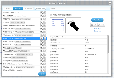
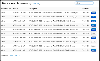
Upverter gives detailed part information during selection
Upverter
- Octopart integration
- Bill of materials with pricing through Octopart
- GitHub integration
- Open format files - export to KiCad, gEDA, Fritzing, Eagle, and more.
- Circuit import
- All changes are recorded
- Custom comment system
- Said to have simulation capability; was unable to get it to work
Circuits.io gives a brief summary of each part
Circuits.io
- Octopart integration
- Bill of materials with pricing through Octopart
- Excellent tutorial videos
- Comments powered by DISQUS
Winner: Upverter
While both applications show part information from Octopart, Upverter's implementation is much more seamless. There is rarely a time where one must visit the Octopart website for additional information. Combined with their powerful open source import/export library, Upverter easily takes the crown for general features. Both apps have good BOM (bill of materials) and commenting implementations. It is worth noting that Circuit.io's comments are powered by DISQUS, and - as usual - they feel like glued on third party controls.
Schematic Capture
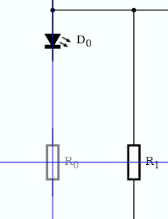
Circuit.io's part alignment feature
Circuits.io
- Innovative part alignment feature
- Generic parts
- Can't manually place wires
- Can't graphically place signal lines
- Cannot change component reference description (particularly annoying because part prefixes cannot be changed without creating a new device)
- No visible grid
- Parts are zero indexed with no way to change
Upverter
- Multiple selection
- Visible grid
- Can edit reference descriptions
- Substandard search tool
Winner: Upverter
With multiple part selection and a visible grid, drawing a circuit in Upverter feels identical to drawing a circuit in a desktop EDA application. Circuits.io departs from the feel of traditional EDA applications, but does so in a very intuitive way. I was particularly impressed with their part alignment tool - something I've enjoyed in GUI designers in the past. The problem with Circuit.io's schematic capture is that expected features like part editing were nowhere to be found. Another big pet peeve of mine was that signal wires could not be moved manually. While I love the idea of having one less thing to worry about, I quickly found myself tweaking the placement of parts just to make the wires look less tangled. Both tools have a lot of potential, but they are going to need some features before they will be usable in larger designs - for example, neither has a way to define a bus with multiple signal wires.
Circuit Board Layout
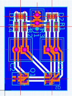
Test layout from Upverter
Upverter
- Multiple selection
- Visible grid w/ snapping
- Custom grid sizes
- Custom vias
- Doesn't give a list of premade packages for all parts
- Polyfills are complicated to use (I had to ask Upverter support how to use them. Apparently this tool was launched recently, so we can expect improvements soon.)
- Had some trouble with generic parts - could not add a footprint for the built-in BJTs
- Cannot restore deleted reference descriptor text
- Added text size cannot be changed
- Part alignment marks are visually intrusive
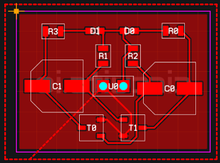
Test layout from Circuits.io
Circuits.io
- Excellent part alignment tool
- Polyfills are easy to create and are awesome by default
- Gives a list of available packages for all parts
- Keeps all text facing the same direction
- Circuit board outline can be dragged around Test layout from Circuits.io
- Initial rat's nest creation is very tedious - parts are stacked on top of each other and can be hard to select (and easy to create traces when attempting to drag)
- No apparent way to add text labels
- Traces are hard to delete (select trace, press escape, press delete)
- Dragging components attempts to keep traces intact. Cute, but often painful.
- Trace widths cannot be changed on the fly
- No way to view net names
Winner: Circuits.io
Circuits.io has a clear lead in circuit board layout. Their friendly part alignment tool is present, along with an intuitive implementation of polyfills (for ground planes, etc). The most glaring issue with both tools was trace placement - traces are universally troublesome to place, move, and tear up. Circuits.io was slightly worse in this regard - to tear up a trace, one must select it, press ESC to cancel drawing a new trace, and then press delete. To be competitive with desktop based layout tools, both websites will need significant work in this area.
Platform
Circuits.io
- Collaboration
- Funding
- Sharing
- Manufacturing (PCBs only)
Upverter
- Collaboration
- Sharing
- Manufacturing (PCBs only)
Winner: Circuits.io
This is a category where web applications really start to show their power. With collaboration and sharing built in from the start, both websites are natural choices for open source hardware. Circuits.io has an advantage in their choice of business model - they are building a manufacturing and funding platform that will enable hobbyists and help fund further development. On the other hand, Upverter's business model is largely centered around people and businesses paying for private design slots and simulation CPU cycles. While their tool is passable for hobbyist use, they are far from a state where they can compete with desktop based tools. Upverter also provides PCB manufacturing facilities, but it feels like a second class feature.
Overall Winner: Circuits.io
Both tools are equally usable and both have their share of annoyances and shortcomings. While it is hard to pick one based on features alone, Circuits.io is an easy choice when the overall platform is considered. Circuits.io currently has a more solid business model than Upverter. Even so, that could change overnight if, for example, Upverter joined up with Tindie as a funding and commerce platform.
To get familiar with each application, I drew a simple 2 transistor LED blinker circuit. I kept the circuit layout single sided. Due to the design of the circuit, a trace must either cross between leads on a component or move to a second signal plane. In both layouts, I routed this trace between the pins of a SOT23 transistor - this goes against best practices, so I would warn against manufacture of either design.
Shout out to CircuitLab for having an excellent web based schematic capture and simulation application.
comments powered by Disqus