A Simple USB Audio Device
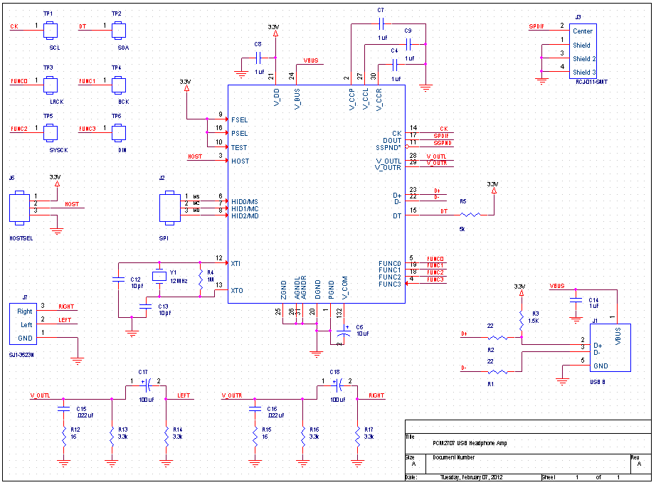
About four months ago, I came across the TI PCM2707. The PCM2707 is a standard USB 1.1 audio IC. As such, it can play audio without any custom drivers. My device closely follows the reference design shown in TI's datasheet. The PCM2707 can play 16 bit stereo audio at a maximum sampling rate of 48kHz. It has a built in 175mW headphone amplifier for analog output. Additionally, it can output S/PDIF and I2S digital audio. The former might be used to connect to a consumer audio receiver, while the latter could be used to interface with a more powerful amplifier IC.
The PCM2707 has a built in 3.3 volt regulator. I was tempted to use this regulator's output to power a separate headphone amplifier, but TI specifically warns against this. Doing so would probably risk blowing the built in regulator or going over USB's 500mA current limit. As I'm not a fan of toasting $10 chips, I opted to stay with the reference design.
The PCM2707 was brought to market in 2003. While it offers simplicity, it sacrifices a number of attractive features present in modern USB audio devices. The USB 1.1 audio standard has provisions for stereo audio at a bit depth of 16 and a sampling rate of up to 48kHz. If you want more, you need a custom driver. Any of these features is likely to require more bandwidth than USB 1.1 can offer, so you probably need a USB 2.0 device, too. As far as I am aware, there is no USB 2.0 equivalent to the PCM2707 on the market - all solutions seem to be based around a processor with a USB hardware interface and a DAC. I didn't want to bother with an unfamiliar MCU, custom drivers, and expensive development kits - so I picked the dinosaur.
Hardware
I did not need any exceptional features, so I opted to use TI's reference design. I copied the schematic into OrCAD and broke out the lines that looked interesting. From OrCAD, I exported a netlist to PADS for hardware layout. (To glue the two pieces of software together, I used the PowerNET netlister.) This workflow was painful to set up, but very efficient once it was operational. I opted to use these two software packages over Eagle because my coworkers are familiar with them.
The layout was scrapped three times before I arrived at my final design - I planned to buy boards from BatchPCB, so I foolishly forced my design into one square inch. By the time I was done carving bits from my design, I had a haphazardly placed double sided board with no access to a number of useful pins. For the first layout iteration, I hand placed all components and hand routed all traces. For the subsequent layouts, I kept the hand placement and autorouted the traces. This saved neither time nor effort - I spent so much time tweaking and optimizing the traces that it would have been faster to route them manually.
In my final design, all resistors and ceramic capacitors are 0603 size. I like 0603 because it offers a good compromise between size and hand-solderability.
Assembly
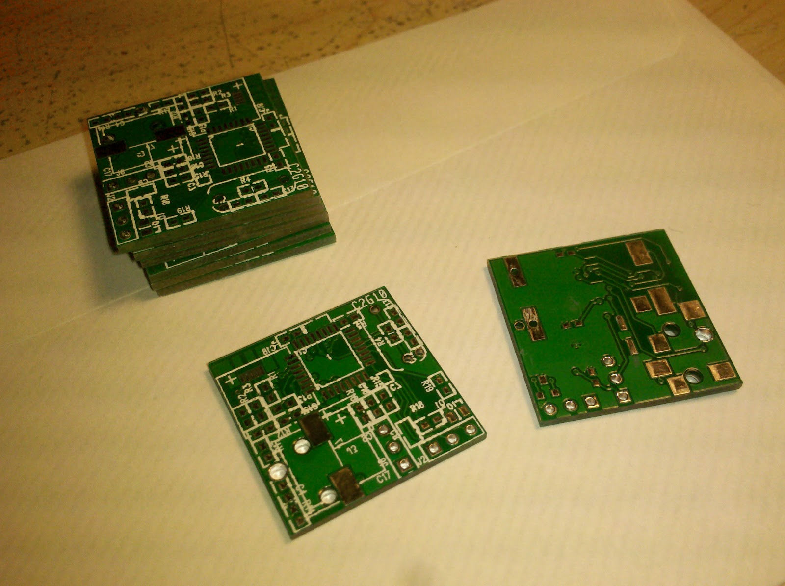
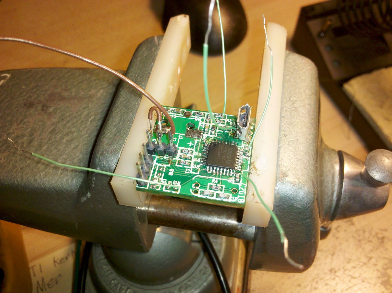
When the boards arrived, I performed a quick inspection. BatchPCB's board house had put the silkscreen for both sides on the top! Additionally, the soldermask was thin and uneven. I wasn't too happy - nonetheless, I hurriedly assembled one and plugged it into a USB port. The PCM2707 on-board promptly let out its magical smoke. After a few hours spent debugging, I determined that my USB footprint was numbered backwards and the data lines were swapped. After soldering a USB cable directly to my board, everything worked as expected.
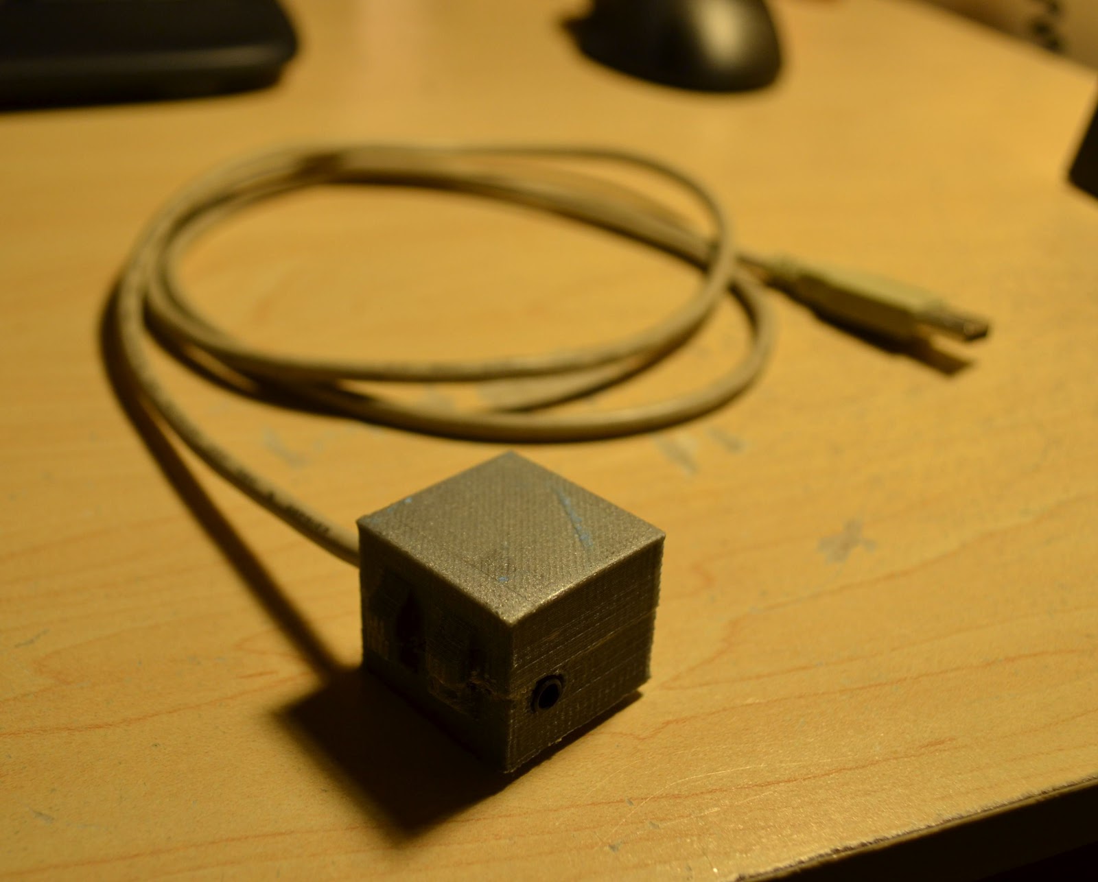
Once I was satisfied that nothing would spontaneously explode, I printed a small case with my reprap. Because I failed to add mounting holes to my PCB, I designed a case that would contact the perimeter of the PCB while avoiding any nearby components. To help avoid any mistakes, I modeled the assembled part and built a box around it.
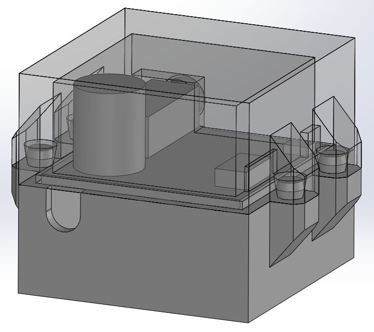
The four small pins visible in the above rendering did not print correctly, so I glued the two halves together.
Performance
This little guy sounds great! The "low res" audio sounds stellar on everything from my pair of Sony MDR-V500s to my friend's Sennheiser HD555s. The device is absolutely silent when no audio is playing. It delivers clean mids and highs and a reasonable amount of bass.
Mistakes
- Micro USB connector on a prototype
- Components right next to the edge of the PCB
- Components on both sides of the PCB
- Autorouted traces
- Minimum size traces (6mil)
- No locating holes or cutouts
- No revision letter (or number)
- Ordered a lot of PCBs to 'make up for' the BatchPCB setup fee
In the future, I will use:
- Mini USB
- 0.1" edge clearance for all non-connector components
- Components on one side
- Larger traces
- Manual routing
- Locating holes
- DorkbotPDX
Added 4/7/2012
I found another bug - the channels are swapped! This issue would be tough to fix by cutting traces, so I solved it by flipping the 3.5mm jack upside-down and wiring its pins to the proper pads. This is fixed in rev B - the files for which will be up as soon as I have verified their integrity.
Added 4/11/2012
Gerbers: http://dl.dropbox.com/u/11414619/Gerbers_R16.zip
Schematic: